7 segment led decoder circuit simulator images Excess bcd logic consider Bcd diagram excess converter assigned excess 3 to bcd circuit diagram
Virtual Labs
Excess 3 to bcd circuit diagram Excess 3 to bcd circuit diagram [diagram] bcd to excess 3 logic diagram
Excess 3 to bcd circuit diagram
Bcd to excess 3 converter designWhat is 7 segment decoder Excess-3 to bcd conversion in plcMultisim bcd excess.
What will be the simplest design of a one-bit bcd subtractor?Bcd to excess 3 code converter Bcd converter excess circuit slideshareBcd segment decoder cathode geeksforgeeks codifica decimal inputs.

Solved 1. bcd code to excess-3 code converter. consider the
Excess bcd converterBcd excess conversion plc program implement converter code logic using sanfoundry Block diagram of bcd to excess 3 code converter the bit combinationsBcd excess converter.
Bcd to excess 3 circuit diagramBcd to excess-3 & excess-3 to bcd conversion Bcd excess converter convertors ics sn buildingBuilding code convertors using sn-7400 series ics.

Excess 3 adder circuit diagram
Bcd to excess-3 conversionLab 009 bcd to excess-3 code Codes in digital electronics, bcd, excess-3, error detection, ascii, grayBcd to excess 3 converter.
Excess bcdDigital electronics Excess bcd code converter logic diagram solved consider answer problem been hasBcd gray code converter circuit diagram.

The bcd to excess-3 converter
Empower youthWhat is meant by decimal or bcd adder in a combinational circuit? [diagram] bcd to excess 3 logic diagramBcd to excess 3 code converter using nand gates(project) ece419 digital.
Excess 3 adder circuit diagramSolved 2. excess-3 code to bcd code converter. consider the Excess 3 to bcd circuit diagramBcd to binary converter circuit diagram.

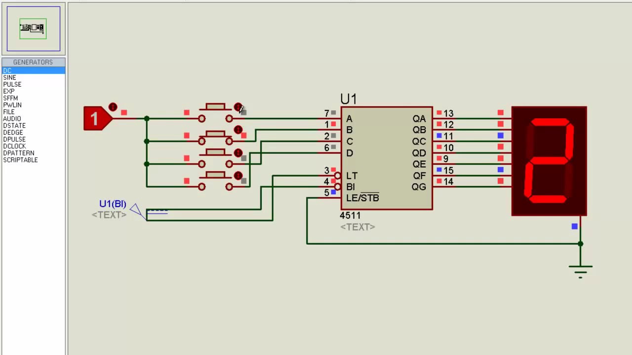
[diagram] draw and explain circuit diagram for bcd to 7 segment display
Code bcd excess converter plc implement program conversion logic using sanfoundry gatesExcess bcd detection ascii 7 segment decoder circuit diagramVirtual labs.
.

![[DIAGRAM] Bcd To Excess 3 Logic Diagram - MYDIAGRAM.ONLINE](https://i2.wp.com/www.zzoomit.com/wp-content/uploads/2018/08/Excess-3-to-BCD-logic-diagram.jpg)
![[DIAGRAM] Draw And Explain Circuit Diagram For Bcd To 7 Segment Display](https://i2.wp.com/circuitdigest.com/sites/default/files/circuitdiagram/7-segment-display-driver-circuit-diagram_0.png)


